![]()
![]()
ESP32 based voice assistant with wake word
Last year (2023) was Home Assistant’s Year of the Voice so I thought there’d be no better way to start 2024 than by building my own Home Assistant powered smart speaker.
It’s based on an ESP32 Lyrat dev board which doesn’t seem to be widely available so you can grab one on Aliexpress (affiliate link) or Amazon US / DE. Have a look at my toolbox essentials for links to the other items used in this project.
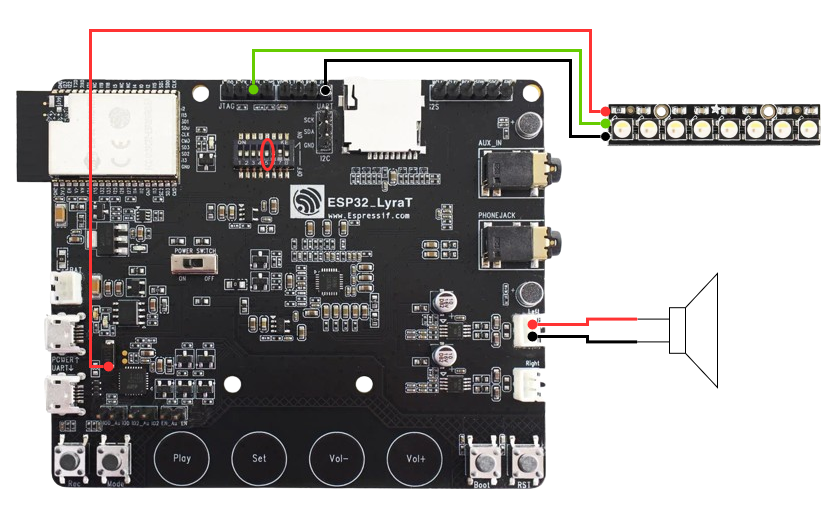
The Lyrat board has two 3w @ 4 ohm audio outputs which is enough for this use case but it means that we’ll want to stick to a pretty small 4 ohm speaker. I wanted the sound quality to be as good as possible without breaking the bank so after a bit of research, I grabbed a Dayton Audio DMA45-4 1.5″ Full-Range Driver for €18 (Amazon – US, UK).
The last item you’ll want is an Adafruit Neopixel Stick (Amazon US, UK). These are great, multi-purpose addressable LED strips and for this project, we’ll use it as an indicator for when the wake word has been detected.
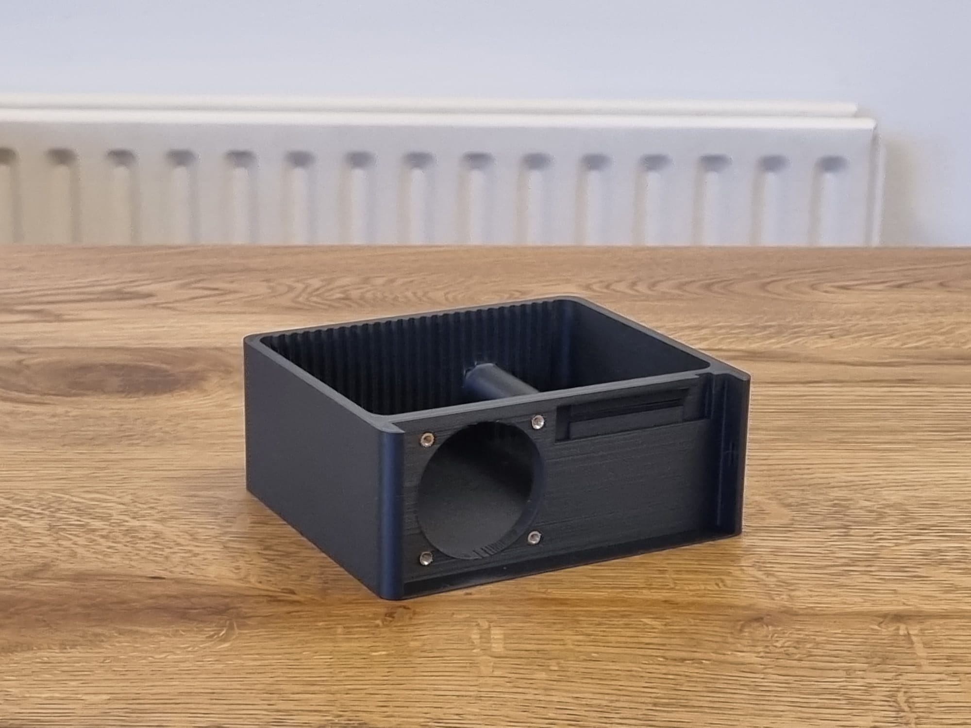
Right, lets get started. Head over to Printables to grab the .stl files for this project. I printed it in eSun matte black PLA (link on my toolbox essentials page) but you can really print it in whatever colour/filament you want.
Once you’ve printed the main body of the enslosure, use a soldering iron to insert four M3 x 5mm brass inserts at the front of the ensclosure for the speaker and glue the port into place at the back of the enclosure. I used a Dremel to ensure that the hole for the port is perfectly round before glueing it in. I found that Loctite Super Glue Power Gel (linked in my toolbox essentials) worked well for this project because it didn’t harden immediately but you’ll want to buy a few bottles of it.
Not pictured – if you can, add some batting to the speaker enclosure before you glue the lid on.
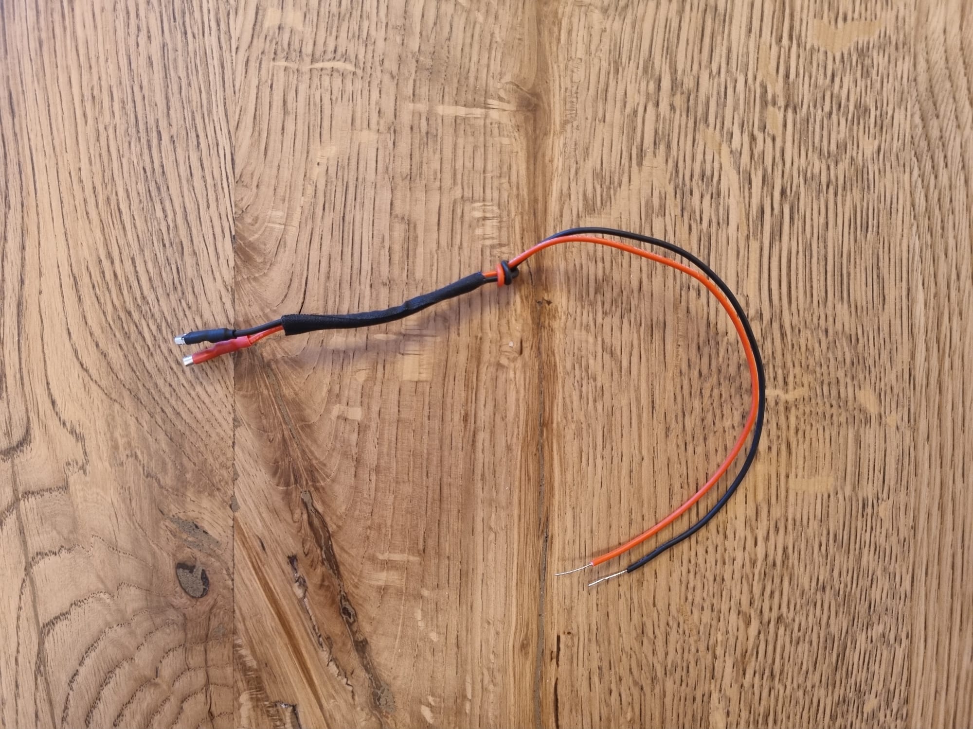
I chose to make the speaker cable out of some 0.5mm2 silicone wire. This speaker requires a small spade connector for the negative and a slightly larger spade connector for the positive connector. Once you’ve made the cable, glue it in to place with the spade connectors on the bottom of the lid. I used hot melt glue which seems to be holding up fine.
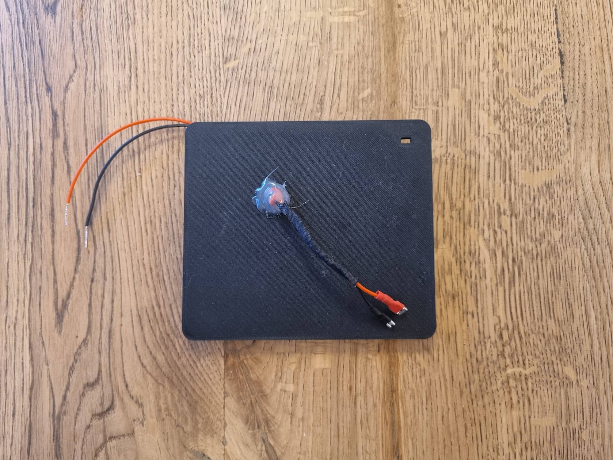
Once the glue has dried, use superglue to stick the lid/midframe onto the top of the speaker enclosure. I used some painters tape to hold align it and a pair of clamps to apply pressure while the glue cures.
After about 10 minutes, the superglue should have cured. Now you can break out the soldering iron again to install six M2.5 x 4mm brass insert nuts – four of them will be installed vertically into the midframe/enclosure lid for the Lyrat board and two more will be installed horizontally to hold the lid on.
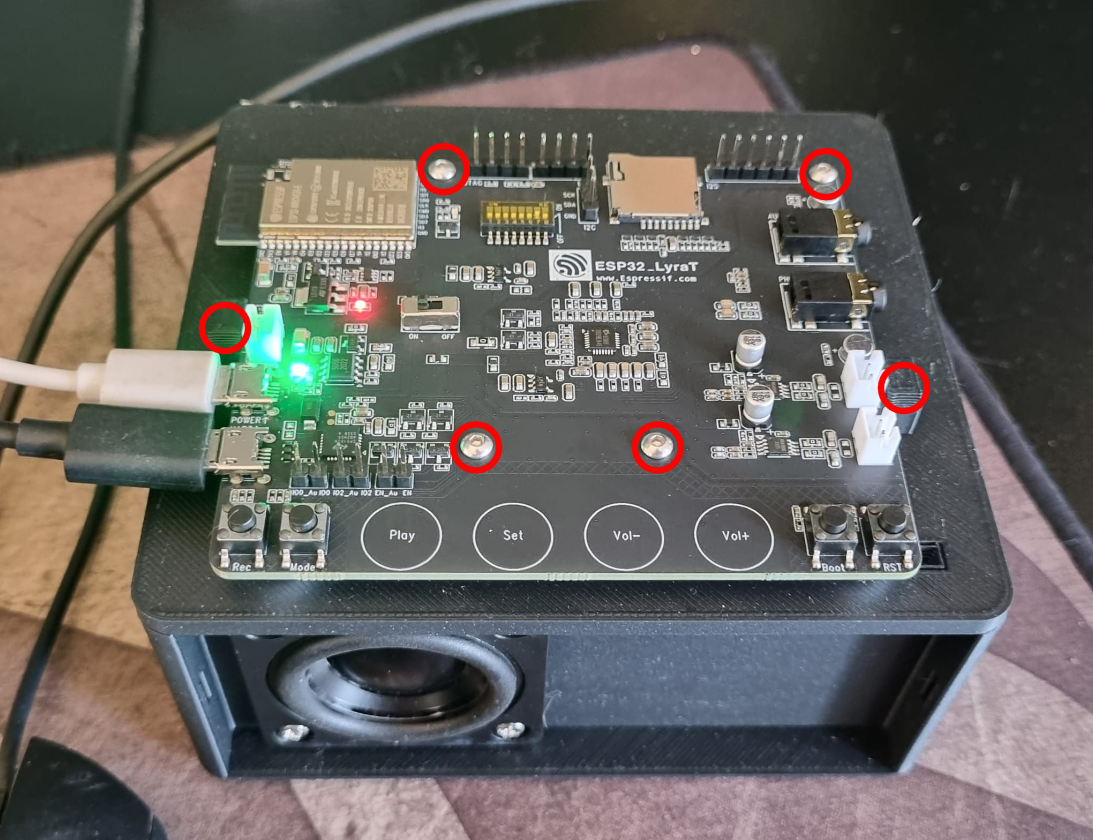
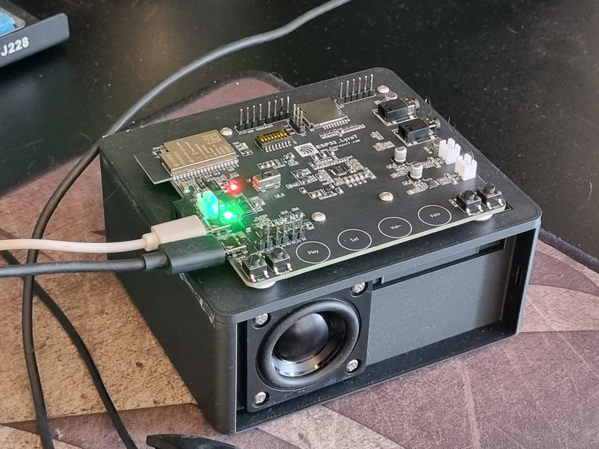
Now it’s time for some wiring! I wanted to keep the enclosure as short as possible so I soldered all of the connections (apart from the Vcc/positive connection for the LED bar) to the bottom of the PCB. The wiring is pretty straight forward but you’ll need to turn on DIP switch #5 which seems to reroute GPIO12 from the micro SD reader to that header pin.
Please don’t do what I did – make sure to install the LED bar into the enclosure before you solder the wires to the Lyrat. I found it easiest to solder the power cables to the right hand side of the LED bar so you only have the data cable that needs to go behind the LED bar.
Once the wiring has been done, you can screw the Lyrat board onto the midframe with 4 x M2.5 x 6mm screws before we move on to flash some firmware onto the ESP32. 🥳 You’ll need two micro USB cables for this – one that will connect the serial port to your computer and one that will power the Lyrat board.
You’ll need an instance of Home Assistant, the ESPHome add-on and a Voice Pipeline to be setup for this. Have a look at Home Assistant’s guide for setting up a voice pipeline. Here is the ESPHome YAML that I used, you’ll want to update certain parts of it like your API encryption key and OTA password before flashing it to the ESP32.
YAML
esphome:
  name: bedroom-speaker
  on_boot:
     - priority: -100
       then:
         - wait_until: api.connected
         - delay: 10s
         - if:
             condition:
               switch.is_on: use_wake_word
             then:
               - voice_assistant.start_continuous:

esp32:
  board: esp-wrover-kit
  framework:
    type: arduino
    version: recommended

logger:

api:
  encryption:
    key: ""<<your key here>>""

ota:
  password: "<<your password here>>"

wifi:
  ssid: !secret wifi_ssid
  password: !secret wifi_password

  # Enable fallback hotspot (captive portal) in case wifi connection fails
  ap:
    ssid: "Speaker Fallback Hotspot"
    password: ""<<your password here>>""

captive_portal:

i2c:
  sda: GPIO18
  scl: GPIO23

external_components:
  - source: github://pr#3552
    components: [es8388]
    refresh: 0s

es8388:

microphone:
  - platform: i2s_audio
    id: mic
    adc_type: external
    i2s_din_pin: GPIO35
    pdm: false
    channel: left

i2s_audio:
  i2s_lrclk_pin: GPIO25
  i2s_bclk_pin: GPIO5

media_player:
  - platform: i2s_audio
    name: speaker
    id: media_player_speaker
    dac_type: external
    i2s_dout_pin: GPIO26
    mode: stereo

switch:
  - platform: gpio
    pin: GPIO21
    name: "AMP Switch"
    id: amp_switch
    restore_mode: ALWAYS_ON

  - platform: template
    name: Use wake word
    id: use_wake_word
    optimistic: true
    restore_mode: RESTORE_DEFAULT_OFF
    entity_category: config
    on_turn_on:
      - if:
          condition:
            not:
              - voice_assistant.is_running
          then:
            - voice_assistant.start_continuous
    on_turn_off:
      - voice_assistant.stop

voice_assistant:
  microphone: mic
  use_wake_word: true
  noise_suppression_level: 2
  auto_gain: 31dBFS
  media_player: media_player_speaker
  id: assist
  on_wake_word_detected:
    - light.turn_on:
        id: led_bar
        brightness: 30%
        effect: "Custom Scan Effect"
        red: 100%
        green: 0%
        blue: 0%
  on_listening:
    - light.turn_on:
        id: led_bar
        brightness: 50%
        effect: "Custom Scan Effect"
        red: 0%
        green: 100%
        blue: 0%
  on_end:
    - light.turn_off:
        id: led_bar

light:
  - platform: neopixelbus
    id: led_bar
    type: GRB
    variant: WS2812
    pin: GPIO12
    num_leds: 8
    name: "NeoPixel Light"
    effects:
      - addressable_scan:
          name: Custom Scan Effect
          move_interval: 100ms
          scan_width: 2

esp32_touch:

binary_sensor:
  - platform: esp32_touch
    pin: GPIO33
    threshold: 1000
    name: "Play"

  - platform: esp32_touch
    pin: GPIO32
    threshold: 1000
    name: "Set"
    on_press:
      then:
        - switch.toggle: use_wake_word

  - platform: esp32_touch
    pin: GPIO27
    threshold: 1000
    name: "Vol Up"

  - platform: esp32_touch
    pin: GPIO13
    threshold: 600
    name: "Vol Down"
Expand
Once the firmware has been installed, you can pop the lid on with two M2.5 x 10mm screws and we’re almost done!
The back of the lid has a cutout for a panel mount USB C connector like this one from Aliexpress. Unfortunately my order didn’t arrive in time but I’ll make sure to post an update when they arrive.
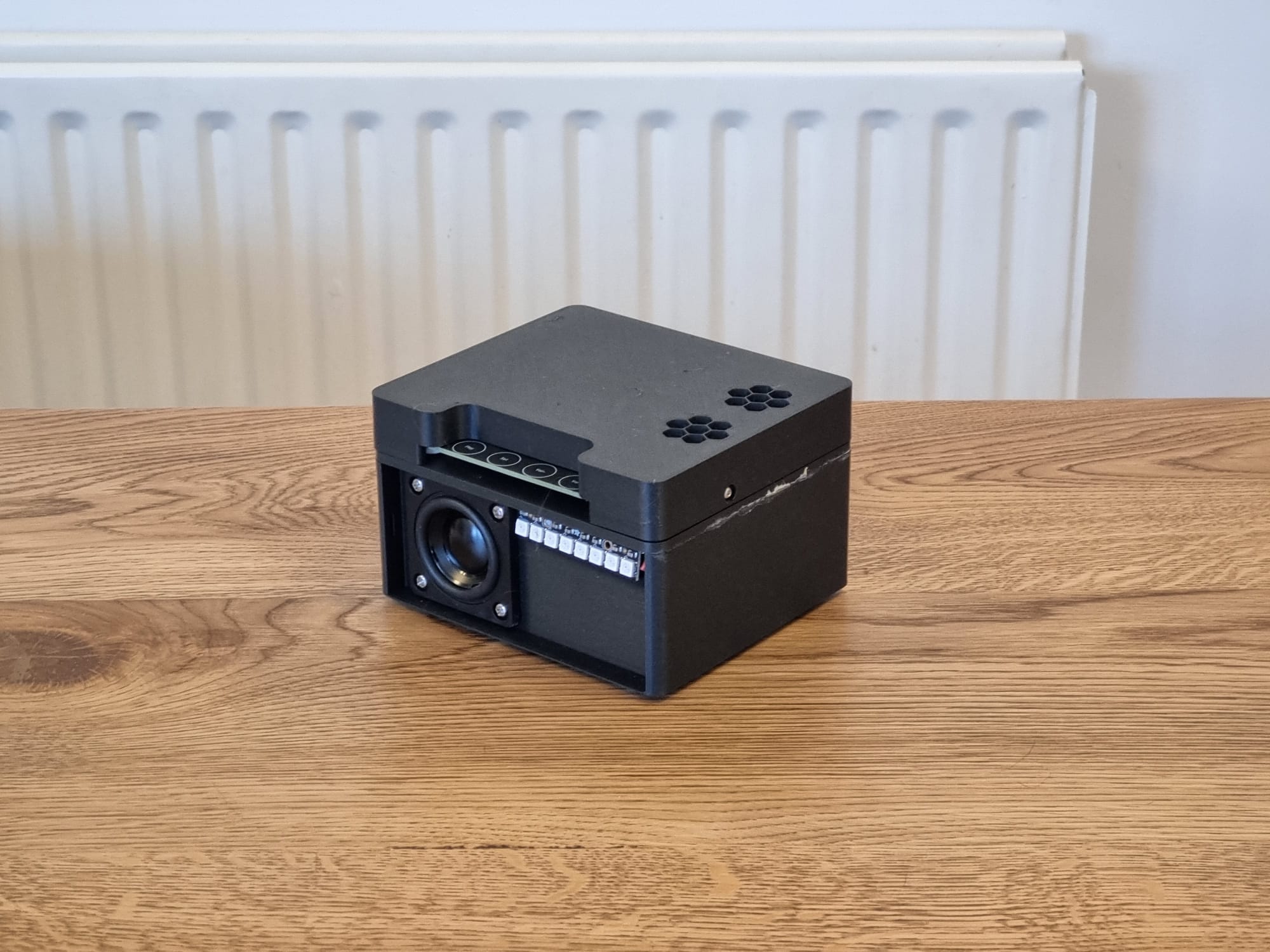
The last, and most fiddly bit is up next – the speaker grille. Print the frame .stl that’s on printables and then glue some black (or whatever colour you want) fabric onto it. I used the same superglue and some clothes pegs to hold the fabric in place while the glue cures.

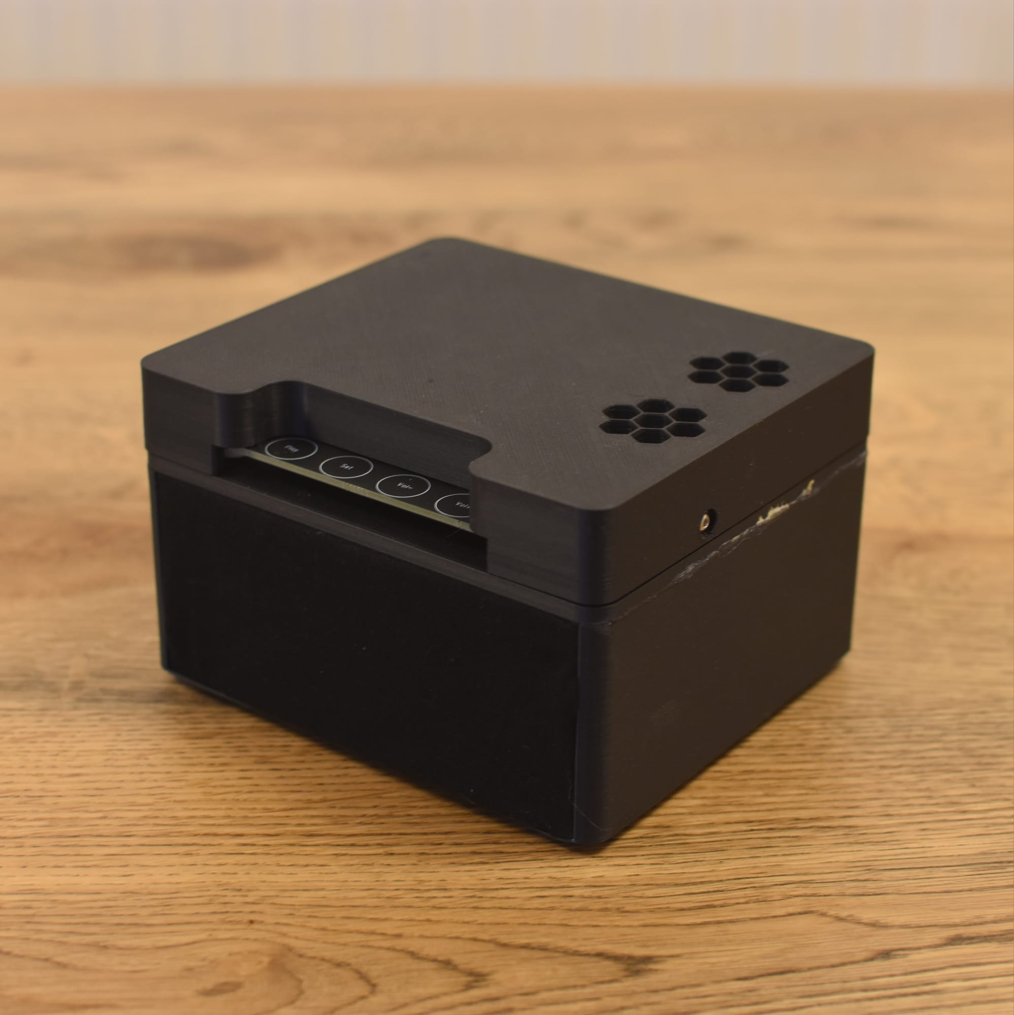
And you’re done! You should now have a local voice assistant that’ll let you control your smart home without the worry of Mr Bezos listening in or the reliance on an internet connection!
Here’s a video of a prototype in action.
*The product links in this post may contain affiliate links. Any commission earned is used to keep the servers running and the gin cool.
Thanks for making it to the end of the post!
I love it. This project made me finally buy a 3d printer. What infill did you use for the speaker box. I coild see reasons for stiff and also for light.
Enjoy the 3d printer!
I used cotton for infill (because it’s what I had on hand) but there are probably better alternatives.
Noticed the ESP32-LyraT is out of stock most places, any recommendation for alternatives?
Yeah, it’s a bit annoying. Have a look on Aliexpress (link in article). Check out Everything Smart Home’s video where he builds one using an ESP32, microphone and audio DAC/amplifier.
Thanks, the version linked in the article from Aliexpess is also out of stock, but was able to find one on the a different site.
Wired but not working yet. My panel mount USB C connector came today and I could not figure out how you were going to wire it into the Vcc and ground. Same places you powered the LED array from? Is that 5V or 3.3V? If you have wired yours, I would appreciate pictures.
Hey Mark, I soldered it to the Vcc and ground pins on the micro USB in that’s used to power the device.
I had a lot of issues with the audio from the speaker being choppy and ununderstandable. Seemed to be chopped up into 1/2 second segments or less.
I looked around for different solutions, maybe reducing the sampling rate of the output. I could not figure out how to do that, but I stumbled on this (https://github.com/home-assistant/core/issues/92969) and replaced the speaker part of the yaml with
speaker:
– platform: i2s_audio
id: media_player_speaker
dac_type: external
i2s_dout_pin: GPIO26
mode: mono
Now I can hear the responses very clearly. Nice speaker selection!
The wakeword and voice recognition are not good yet, but I I will be looking at it more closely.
If you have made any improvements in the yaml configuration, I would love hearing about them.
Was there anything special needed to get ESPHome to flash the ESP32? The webpage is reporting back that it can’t find any device.
Tristam, thank you so much for this!
I was able to source a couple of these boards from Mouser electronics in the states.
I did have an issue getting this running, and I wanted to share what I found in case it is helpful to others: my device had very (very very very) choppy audio and would not recognize any keywords. I had to disable the esp32_touch components (essentially comment from that line down) before I could get the device to work. It worked flawlessly after that.
I had the same thing happen. Same fix. Were you able to get them working again?
No, I wasn’t able to. I didn’t really put any effort into it though.
I left a note about this on the ESPHome discord, but it didn’t really get any traction.
Is it not damaging to the amplifier to have only one speaker connected?
So the deafening silence implies that no one knows, (or cares). But thanks for taking an interest.
My unit has been in operation and powered on for nearly a couple of months now and so far there has been no damage.
Sadly this board doesn’t seem to be available any more. I’ve tried to get it working with the ESP32-LyraT Mini but that uses different audio codecs (ES8311 for output, ES7243 for input), there’s no first party support for either and the third party code I found for the ES8311 didn’t seem to work for me.