![]()
![]()
ESPHome voice assistant with local wake word
Update 2024/11/15: I have made some updates to the ESPHome .yaml config in an attempt to reduce static noise on the speaker output that some makers have reported. It’s hard to repeat this experience consistently but these changes seem to help a bit. I recommend you connect the MAX98357 audio amp/dac to 5V instead of the 3.3v that I used in another attempt to reduce unwanted noises.
At the beginning of 2024, I built a voice assistant to celebrate the end of Home Assistant’s Year of the Voice and the beginning of an era of locally controlled voice assistants.
The team at Home Assistant team has introduced microWakeWord which allows ESP32-S3 microcontrollers to detect the wake word (e.g. Alexa or Hey Jarvis) on the device and LLM’s as conversation agents which Home assistant uses as “the brains of your assistant and will process the incoming text commands“. These powerful new features are paving the way for Home Assistant to replace your Google Home and Amazon Echo smart speakers.
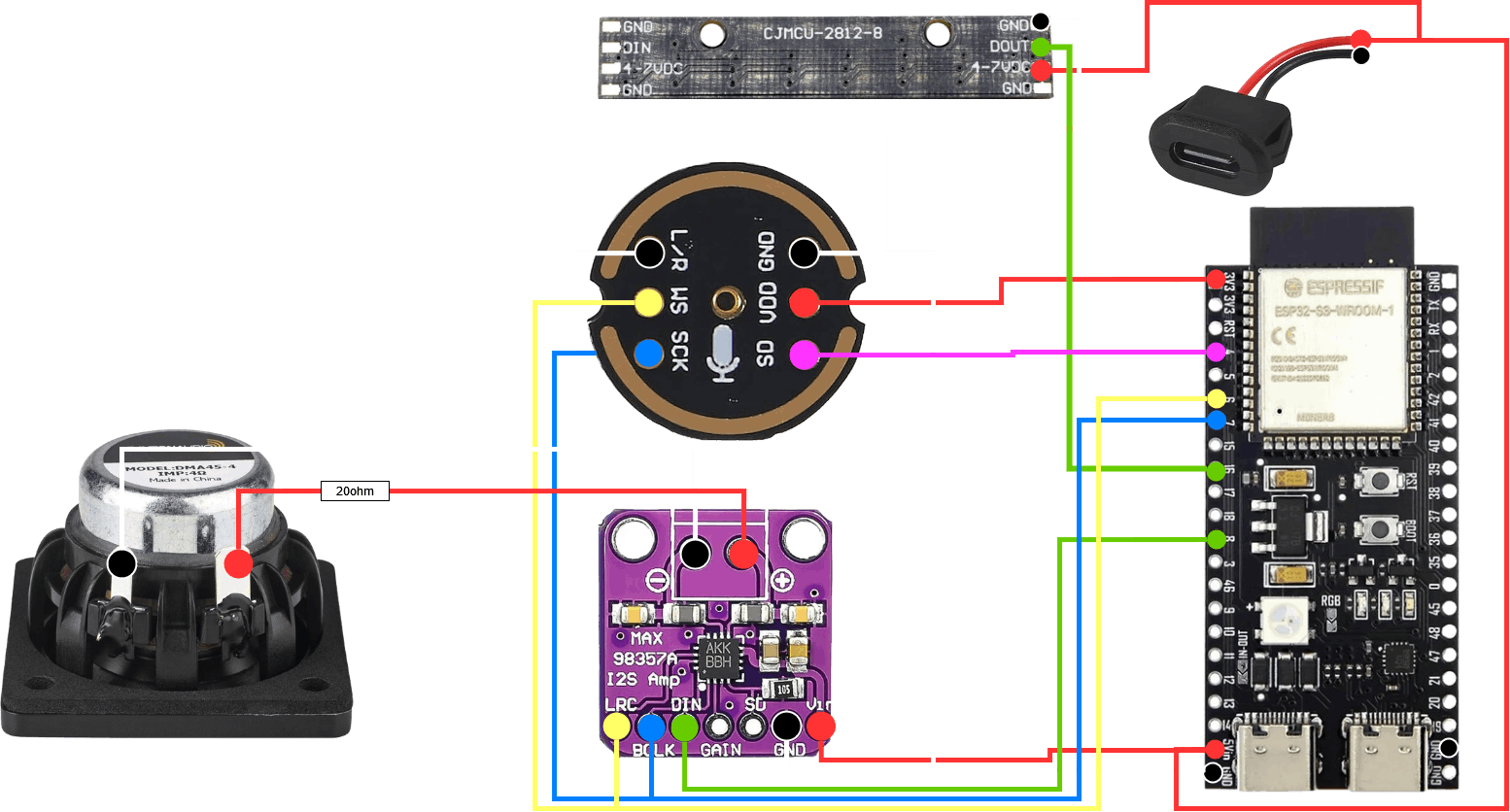
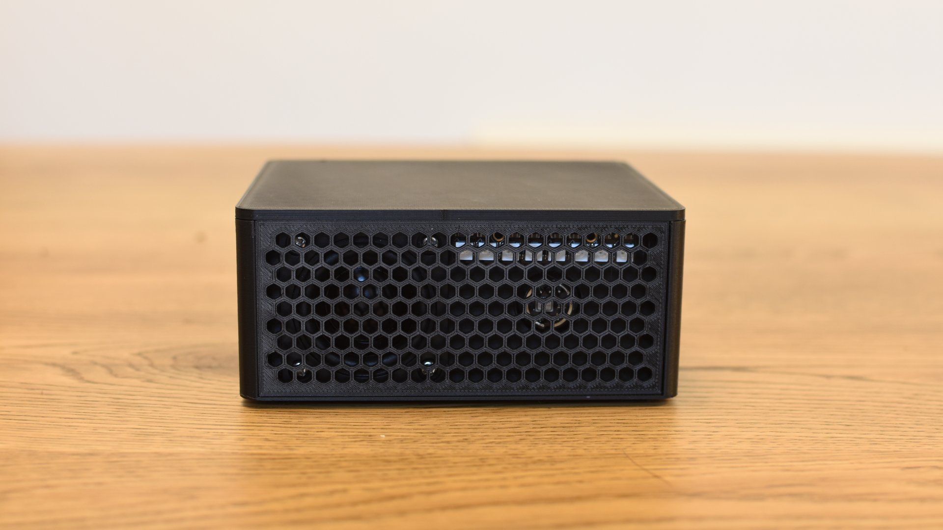
The voice assistant that we’re going to build is based on three key devices – an ESP32-S3 (Amazon US, UK, DE) which is the brains of the operation, a MAX98357 audio amplifier (Amazon US, UK, DE) and an INMP441 microphone (Amazon US, UK, DE). These are combined with a 3D printed enclosure, a Dayton Audio DMA45-4 speaker (Amazon – US, UK) and a WS2812 based RGB LED Stick (Amazon – US, UK, DE) give you a locally controlled voice assistant for less than US$50.
To get started, head over to my Printables project to download the .stl files so you can print the enclosure. I printed it in eSun matte black PLA (linked in my toolbox essentials).
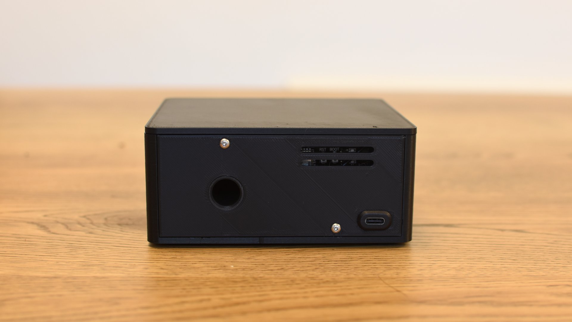
Assembling the enclosure – you’ll want to start off by inserting the various brass insert nuts (linked in my toolbox essentials). There are four M3 x 5mm inserts in the front of the enclosure for the speaker to screw into, two M2.5 x 4mm inserts for the amplifier to screw into at the back of the enclosure and two M2.5 x 5mm inserts for back panel to screw into. I’d recommend you don’t glue the lid onto the enclosure or the port in place until you’ve connected everything and tested it.
Wiring – Now we can start connecting all of the components. Here is the wiring diagram for the build. I added a 20ohm resistor to the speaker to make it a little quieter but you could add a 100k ohm resistor between VCC and gain on the MAX98357 audio amplifier to drop the output by 6db. I used 20 AWG/0.5mm2 stranded silicone wire for all of the connections (once again, this is linked on my toolbox essentials page).
Time for some code – This project is based on ESPHome in Home Assistant so here is the .yaml config that I used. There are tons of great ESPHome setup guides so I’ll leave that part to you.
YAML
esphome:
  name: "smart-speaker"
  friendly_name: smart-speaker
  name_add_mac_suffix: false
  platformio_options:
    board_build.flash_mode: dio

esp32:
  board: esp32-s3-devkitc-1
  variant: esp32s3
  framework:
    type: esp-idf

    sdkconfig_options:
      CONFIG_ESP32S3_DEFAULT_CPU_FREQ_240: "y"
      CONFIG_ESP32S3_DATA_CACHE_64KB: "y"
      CONFIG_ESP32S3_DATA_CACHE_LINE_64B: "y"
      CONFIG_AUDIO_BOARD_CUSTOM: "y"

# Enable logging
logger:

# Enable Home Assistant API
api:
  encryption:
    key: "<<your key here>>"
  on_client_connected:
        then:
          - delay: 50ms
          - micro_wake_word.start:
  on_client_disconnected:
        then:
          - voice_assistant.stop:

# Allow Over-The-Air updates
ota:
 - platform: esphome

wifi:
  ssid: !secret wifi_ssid
  password: !secret wifi_password

captive_portal:

web_server:

psram:
  mode: octal
  speed: 120MHz

light:
  - platform: esp32_rmt_led_strip
    id: led_ww
    rgb_order: GRB
    chipset: ws2812
    pin: GPIO16
    num_leds: 8
    rmt_channel: 0
    name: "LED bar"
    effects:
      - pulse:
      - addressable_scan:
          name: scan
          move_interval: 100ms
          scan_width: 1

switch:
  - platform: template
    id: mute
    name: "Mute microphone"
    optimistic: true
    on_turn_on:
      - micro_wake_word.stop:
      - voice_assistant.stop:
      - light.turn_on:
          id: led_ww
          red: 100%
          green: 0%
          blue: 0%
          brightness: 30%
      - delay: 2s
      - light.turn_off:
          id: led_ww
      - light.turn_on:
          id: led_ww
          red: 100%
          green: 0%
          blue: 0%
          brightness: 30%
    on_turn_off:
      - micro_wake_word.start:
      - light.turn_on:
          id: led_ww
          red: 0%
          green: 100%
          blue: 0%
          brightness: 60%
          effect: fast pulse
      - delay: 2s
      - light.turn_off:
          id: led_ww

i2s_audio:
  - id: i2s # For microphone
    i2s_lrclk_pin: GPIO6  #WS
    i2s_bclk_pin: GPIO7 #SCK

microphone:
  - platform: i2s_audio
    id: va_mic
    adc_type: external
    i2s_din_pin: GPIO4 #SD
    channel: left
    i2s_audio_id: i2s
#   pdm: false
#   bits_per_sample: 32bit

output:
  - platform: gpio
    pin:
      number: GPIO8
      allow_other_uses: true
    id: set_low_speaker

speaker:
    platform: i2s_audio
    id: va_speaker
    i2s_audio_id: i2s
    dac_type: external
    i2s_dout_pin:
      number: GPIO8 #DIN Pin of the MAX98357A Audio Amplifier
      allow_other_uses: true
    channel: mono
    bits_per_sample: 32bit
    sample_rate: 16000

micro_wake_word:
  models:
    - model: hey_jarvis
  on_wake_word_detected:
    - voice_assistant.start:
    - light.turn_on:
        id: led_ww
        red: 100%
        green: 100%
        blue: 100%
        brightness: 30%
        effect: scan

voice_assistant:
  id: va
  microphone: va_mic
  speaker: va_speaker
  noise_suppression_level: 2.0
  volume_multiplier: 4.0
  on_stt_end:
       then:
         - light.turn_off: led_ww
  on_error:
          - micro_wake_word.start:
  on_end:
        then:
          - light.turn_off: led_ww
          - wait_until:
              not:
                voice_assistant.is_running:
          - micro_wake_word.start:
Expand
Time for some testing. Your speaker should look somewhat like this now. I’ve used some hot glue to secure the connectors for the microphone and fill the gaps around any wires that pass through the enclosure. Hopefully it works and you can control your Home Assistant Entities. Note that the USB C connector is temporarily connected here – you’ll need to pass it through the hole in the back panel before permanently connecting it to the ESP32.
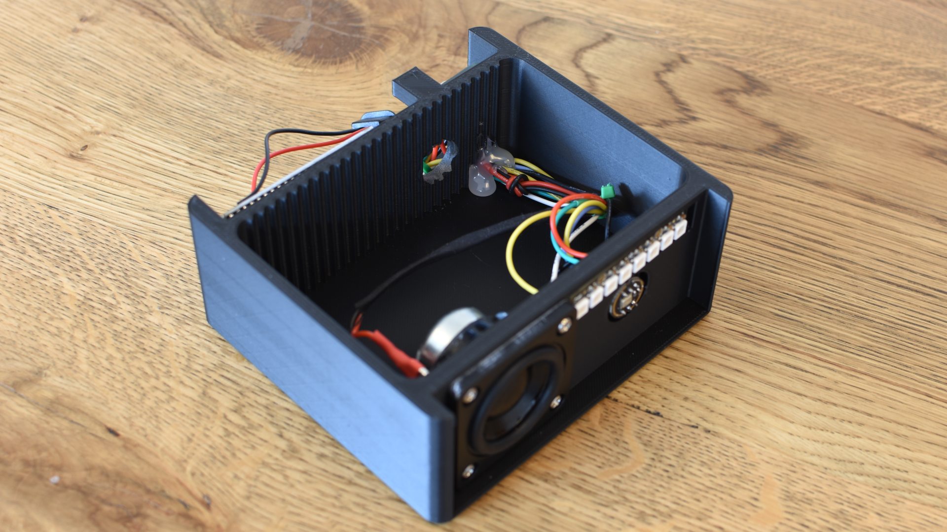
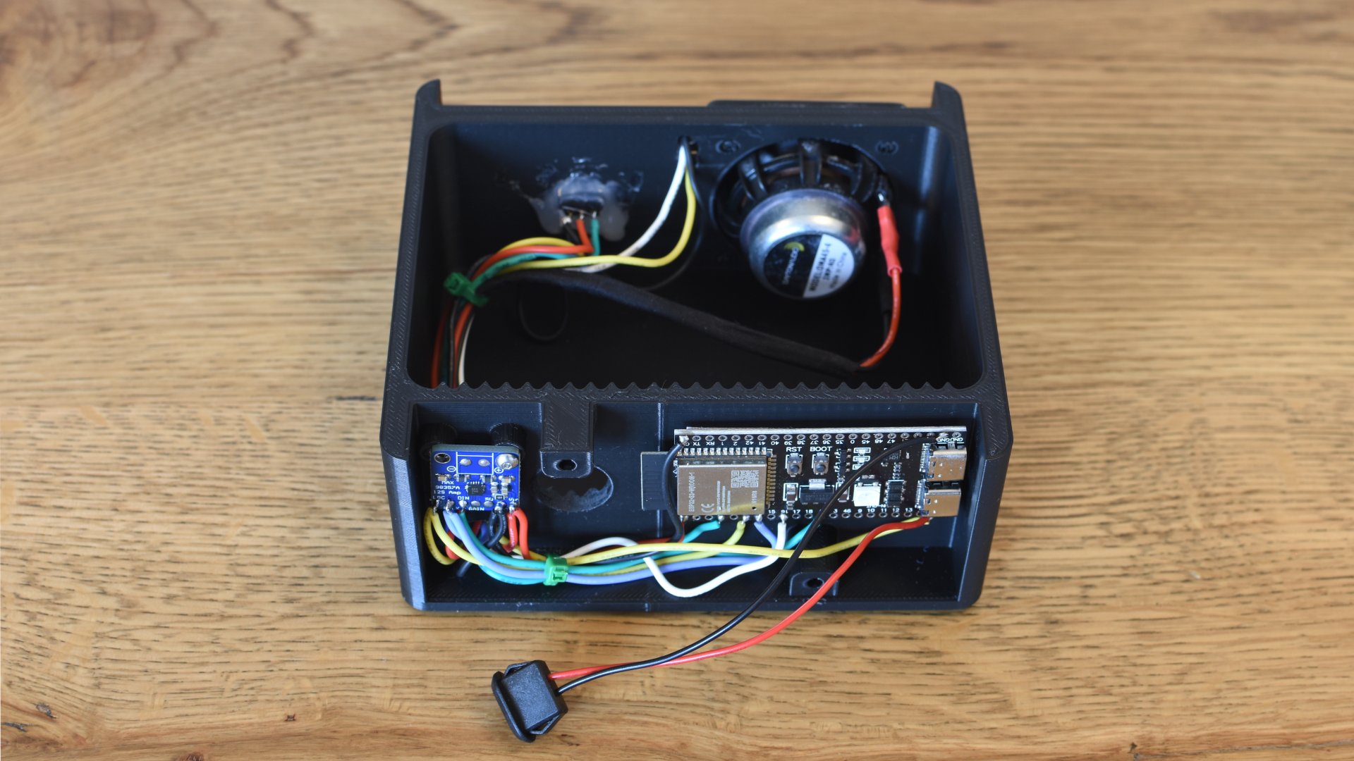
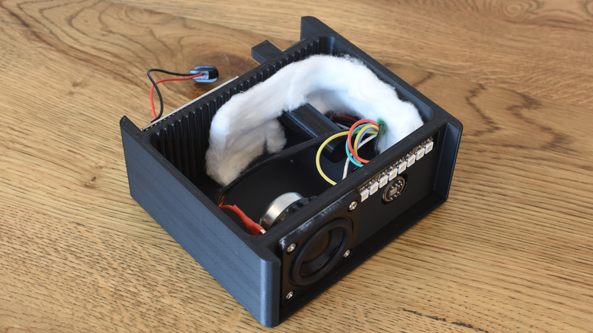
If everything works as expected, you can add some batting to the inside of the enclosure to help with acoustics and then glue the port and lid into place. I used some gorilla glue that is designed to work with PLA. The speaker is held in with four M3 x 8mm screws and both the amp and the back panel are held in with two M2.5 x 5mm screws.
Lastly, here’s a short video of it in action.
*The product links in this post may contain affiliate links. I donate 20% of these earnings to the Good Work Foundation to help innovate learning in South Africa’s rural communities.
Thanks for making it to the end of the post!


Thank for the write-up! I was looking for something like this.
If I would like to run in MIC only mode, can I leave out the audio amplifier or is the amplifier necessary for the setup to work?
Hey Patrick, looking through the ESPHome docs (https://esphome.io/components/voice_assistant.html), it looks like the speaker component is optional so you’ll be fine to build one without a speaker.
Good luck!
This write-up is awesome! Keep up the good work! I’ve been looking for something like this.
I just got all my hardware yesterday, and I started soldering. One problem I’m having is that whenever the microphone is on (when the device is not muted), there is a loud buzzing sound coming from the speaker. I’m wondering if this could be a grounding issue since it subsides if I could the ESP32 module. Any other ideas?
Weirdly enough, it seems it only buzzes the speaker when the device first turns on and starts it’s wake-word loop. I do any voice command, and the buzzing stops.
Minor comment – your LEDs are connected to DOUT – that’s not gonna work, they need to be connected to DIN 🙂
Came here to ask why my LED did not work – thanks for this!
Now I need to figure out why I can’t get it to DO anything, other than start the LEDs when I say Hey Jarvis!!
How’s the range? I’ve been following these projects for a while now with the intent to migrate from a home full of echoes to HA with homebrew smart speakers for wake word but the holdup has mostly been that nothing we can slap together in this price range can pick up the commands from 60ft away in another room like the echo devices can, nor respond with good volume to hear responses. I can’t wait until we can make stuff at that level
Awesome. Any chance of software gain control, either with the MAX98357 or a similar part?
I’m not knowledgeable enough to be able to answer your question, but I did see a pin on the MAX98357 labeled gain. I assume that can be used to do wat you want (I’m going to try getting it to, once I get the parts and get a testing rig set up)
Oops, I posted below, but just found the reply button. You can control the gain of the input signal using the GAIN pin on the MAX98357. The datasheet breaks it all down, but here’s the gist:
15 dB: Connect to GND through a 100kΩ ±5% resistor
12 dB: Directly connect to GND
9 dB: Unconnected (floating)
6 dB: Connect to VDD
3 dB: Connect to VDD through a 100kΩ ±5% resistor
Software volume control (output signal amplitude) is also possible via I2S, but it looks like it’s not currently implemented in ESPHome’s i2s_audio component. There is a third party “external component” for ESPHome though that looks like it has volume control:
https://github.com/gnumpi/esphome_audio/tree/main
Disclaimer: I’ve never used ESPHome, and therefore haven’t tested any of this, so ya know, here be monsters and whatnot.
Why glue the lid on instead of making it removable? Also, acoustics might improve with a series of internal baffles 3d printed (like a tuned port or something).
This is great! Thanks for writing it up.
I just printed the enclosure and there is no hole in the cutout for the LED strip for the connectors to pass through. A drill will fix it but there should be a hole there I believe. Also, it seems the cutout for the speaker is 2-3 mm too low for the speaker to be centered in it.
Should have used an ESP-32 with an onboard battery charger and added a lithium battery so the device would still work when power is out. Something like an Adafruit ESP32 Feather
I get a lot of errors when I try to compile the code.
Have it all assembled, it responds to commands properly, but nothing is output from the speaker. The MAX98357 is receiving 3.3v, I can detect a signal on the data line when ESP32 is sending audio, and obviously the i2s pins are working b/c they’re bound to the mic as well and that is functional.
Really, my question is: should I just assume the MAX is bad or does anyone have any ideas for add’l testing?
Did you ever find a solution, I just hooked everything up and checked it all with a multimeter and everything is good. No sound coming out of speaker though
Thanks for your response, turns out the MAX98357 was DOA. The one thing I didn’t order multiple quantities of (obviously). Got a new one (3) and it worked a charm. Thanks again for all of your work on this!
I have the same issue and I’m waiting for the next one:)
Thank you for this write-up! I’m in the process of putting one together for myself.
Which USB-C connector did you use? I don’t see it listed in the article or the Toolbox essentials page.
I think I found a similar USB C bracket for the enclosure: https://www.aliexpress.us/item/3256805858091014.html
Andrew
Cool project! I don’t use ESPHome, so I’m not sure whether it’s feasible here, but the MAX98357 supports software volume control over I2S.
The GAIN pin on the MAX98357 lets you boost the input signal prior to amplification.
I appreciate the simplicity of it, but adding a resistor in series with the speaker on the output side is a bad idea for various reasons.
Hi, I saw your comment about the resistor is a bad idea? May I ask why and what’s the solution?
It’s not a huge deal, and certainly would work, but it’s not terribly efficient. Also, it could cause degraded audio quality and frequency response due to the added impedance.
The solution is to use software volume control. See my other reply in another thread above for more info.
I can’t see any way to control it in the docs (https://esphome.io/components/speaker/i2s_audio), how can I do it?
I go into more detail in another reply I made above. You have to use an “external component” in ESPHome.
I really appreciate the work you have done here. Because it ” worked” fairly easily as a simple Voice Assistant, I embarked on making something more complicated (media player functionality) based on this work. I plan to go further and remix the 3D Printer file to use less glue and be more intuitive to put together. So far I have something that works fairly well for me, but there’s still a lot of work I want to do you can follow my progress on GitHub. I also fixed your PNG to signify the proper PIN usage for the WS2812, you have it going to DOUT and not DIN. In any case thank you!
https://github.com/JMiahMan1/Home-Assistant-Smart-Speaker/tree/main
Somehow the speaker is cracking like crazy, LED seams to be working but no wake word seems to be detected. I’m a bit puzzled what I did wrong, checked my soldering and even switch microphone and MAX98357.
Hi,
I’m having problems getting the speaker for a reasonable price. Can anyone recommend a similar and fitting speaker available at aliexpress?
I just finished mine up and got these. Seems to work pretty well, though quiet (used a 20ohm resistor as mentioned in the instructions) and I’ll need to figure that out. It does not fit the printed screw holes, so I just hotglued it to the case.
https://www.aliexpress.us/item/3256805925989372.html
The Dayton speaker is also available at Microcenter for cheaper than Amazon.
I was getting the following error:
“PSRAM ID read error: 0x00000000, PSRAM chip not found or not supported, or wrong PSRAM line mode:
In case anyone buys the ESP32-S3 from the Amazon links above, they are N8R2 variants (2mb PSRAM). The provided configuration is for a N8R2 (see pictures). If you have an N8R2 try changing the mode to ‘quad’, it fixed it for me.
psram:
mode: quad
Am I mistaken or is micro-wakewords V2 out. You should be able to do this with a vanilla ESP32 now. I say should because I haven’t been able to get it to work. Works find with open wake word detection on the server, but MicroWW doesn’t respond. Compiles & uploads, but that’s all.
Hey, Nevermind!
I just go t it to work on my ESP32DEV board (wroom 32). I think its better and faster than streaming to openWW on the server. I was going to print a case like yours, but I figured I would just pickup a $4 portable speaker from GoodWill. It already has the speakers, and some LEDs to light when the WW is detected. USB port & buttons too! I’m throwing in a charger and 18650 battery to make it truly wireless and portable.
Thanks for your nice write-up!
Thank you very much for this post. I was stuck to create a voice satellite with ESPHome. WIth your post I succeeded.
I have used an ESP32S3 Supermini. Additionally to your config I have used seperate I2S channels for the mic and the speaker since the S3 has two I2S channels.
i2s_audio:
– id: i2s_mic # INMP441
i2s_lrclk_pin: GPIO1 # INMP441: WS
i2s_bclk_pin: GPIO2 # INMP441: SCK
– id: i2s_amp # MAX98357A
i2s_lrclk_pin: GPIO4 # MAX98367A: LRC
i2s_bclk_pin: GPIO5 # MAX98367A: BLCK
speaker:
platform: i2s_audio
id: va_speaker
i2s_audio_id: i2s_amp
dac_type: external
i2s_dout_pin: GPIO6 # DIN Pin of the MAX98357A Audio Amplifier
channel: mono
microphone:
– platform: i2s_audio
id: va_mic
adc_type: external
i2s_din_pin: GPIO3 #SD pin on the INMP441
channel: left
pdm: false
i2s_audio_id: i2s_mic
bits_per_sample: 16 bit
I did that because in a previous build I have used an ESP32C3 Supermini which has only one I2S audio channel. I got much noise and it never worked. With your post I have discovered the reason why it didn’t worked and it had nothing to do with the ESP32C3. So I will retry with the C3 to get it working and if there is some noise.
With the S3 i get a little backfround noise when the answer is played. No noise at start or when it idles.
I could ask for Yaml for ESP32 C3 Super Mini /GPIO etc/