![]()
![]()
Using a pulse meter with Home Assistant to read your smart electricity meter
We recently moved into a house that has an ESB issued smart electricity meter (Kamstrup model 8660) in the utility cupboard outside of the house. Unfortunately the smart meter has no direct integration with Home Assistant so I needed to get creative with a way to report real time electricity usage to Home Assistant.
Parts list:
- Wemos D1 mini (Amazon – US, UK, DE)
- Light Dependent Resistor (LDR) (Amazon – US, UK, DE)
- Tristam’s toolbox essentials
You can find the .stl for the LDR enclosure on Printables here.
The hardware
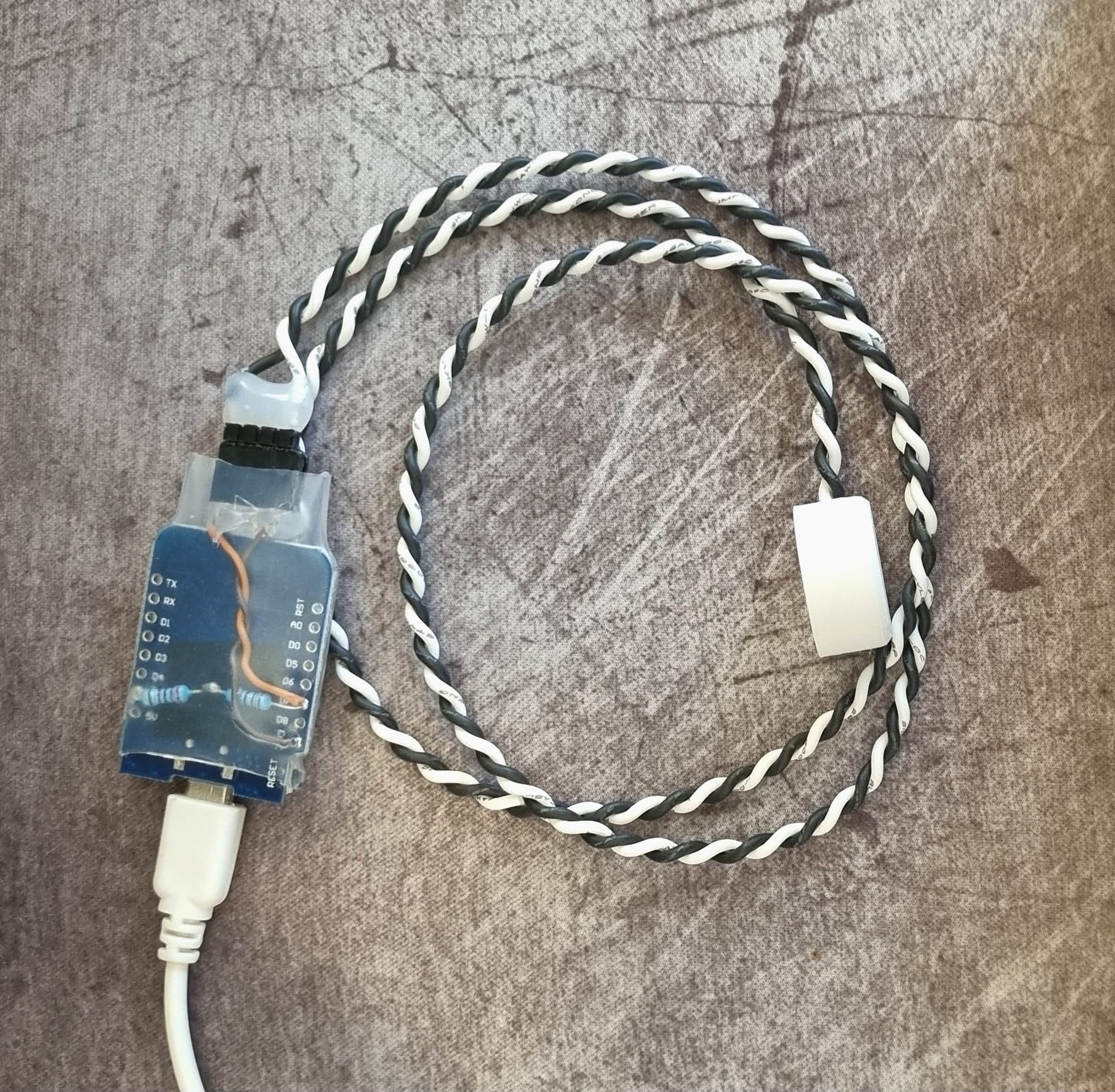
The hardware & physical build for this one is relatively straight forward. Below is a wiring diagram which shows how to connect the Light Dependent Resistor (LDR) to the Wemos D1 mini. I added a set of PCB headers to the Wemos so that I can disconnect the LDR if need be.
Step 1– Use a 3D printer to print the LDR mount, the .stl is linked above. I printed it out of white eSun PLA with 20% infill but you can use pretty much any filament for this.
Step 2 – Solder the 10k ohm pulldown resistor and short leads to the PCB header to the Wemos. You can use the Wemos’ built in pulldown resistor if you want but I chose not to.
Step 3 – Trim the legs on the LDR to about 5mm and solder one wire to each of them. The length of the wire will depend on your installation. Run the wires through the hole in the 3D printed LDR enclosure and use a bit of hot melt glue to secure the LDR in the enclosure. I used a drill to twist the cables together. Solder the male PCB header onto the end of the LDR’s wires and insulate them with some heat shrink tubing or hot melt glue.
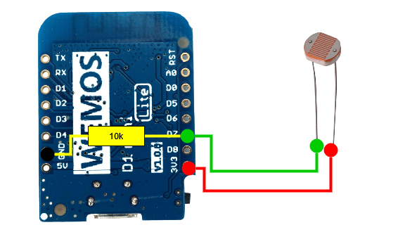
Step 4 – Mount the LDR to your electricity meter – I used a ring of blu tack to secure the sensor to the meter and block out any surrounding light from affecting the readings.
Power consumption
Since I don’t have an easy way to get power to the Wemos D1 mini in the utility cupboard, I’m going to try running it from a 20 000mAh (77Wh) Samsung power bank that I had lying around. Without any tweaks, the Wemos draws about 0.09A @ 5v (roughly 0.45w) but after enabling wifi light power saving, that dropped to 0.04A @ 5v (roughly 0.2w) which means that the 77Wh power bank should last 385 hours or just over 16 days – time will tell.
The firmware
For this project, we’ll use ESPHome to connect the Wemos D1 mini to Home Assistant. There are plenty of online guides how to set that up so it won’t be covered in this article.
Step 1 – Connect your Wemos D1 mini to your computer using a USB cable
Step 2 – Head over to your instance of Home Assistant (I’ve found Google Chrome to be the best browser for this) and go to Settings -> Add-ons -> ESPHome -> Open Web UI and click + New Device. Open ESPHome Web because this is what you will use to flash your esphome config onto your Wemos D1 mini. Follow the prompts to get your device setup and connected to your wifi.
Step 3 – From the ESPHome dashboard in Home Assistant, click Edit on your device and add the code below to your config. Once you’ve added it, click Install -> Wirelessly to write the new config onto your device.
1. (optional) Allow the wifi chip to enter light power saving mode
2. (optional) Set a static IP to reduce the wake time and reduce power consumption
3. Setup the sensor – this config may vary between devices that you’re trying to read but this is generally a good starting point.
wifi:
  ssid: !secret wifi_ssid
  password: !secret wifi_password
  power_save_mode: LIGHT #Included to reduce wifi power consumption

  manual_ip:
    static_ip: 192.168.10.8 #Update me
    gateway: 192.168.10.1 #Update me
    dns1: 192.168.10.2 #Update me
    subnet: 255.255.255.0 #Update me

sensor:
  - platform: pulse_counter
    pin: 13
    internal_filter: 100ms
    count_mode:
      rising_edge: DISABLE
      falling_edge: INCREMENT
    unit_of_measurement: 'kW'
    device_class: power #This is important
    name: 'Current Grid Consumption'
    filters:
      - multiply: 0.06  # (60s/1000 pulses per kWh)
Creating a sensor to track cumulative & daily usage
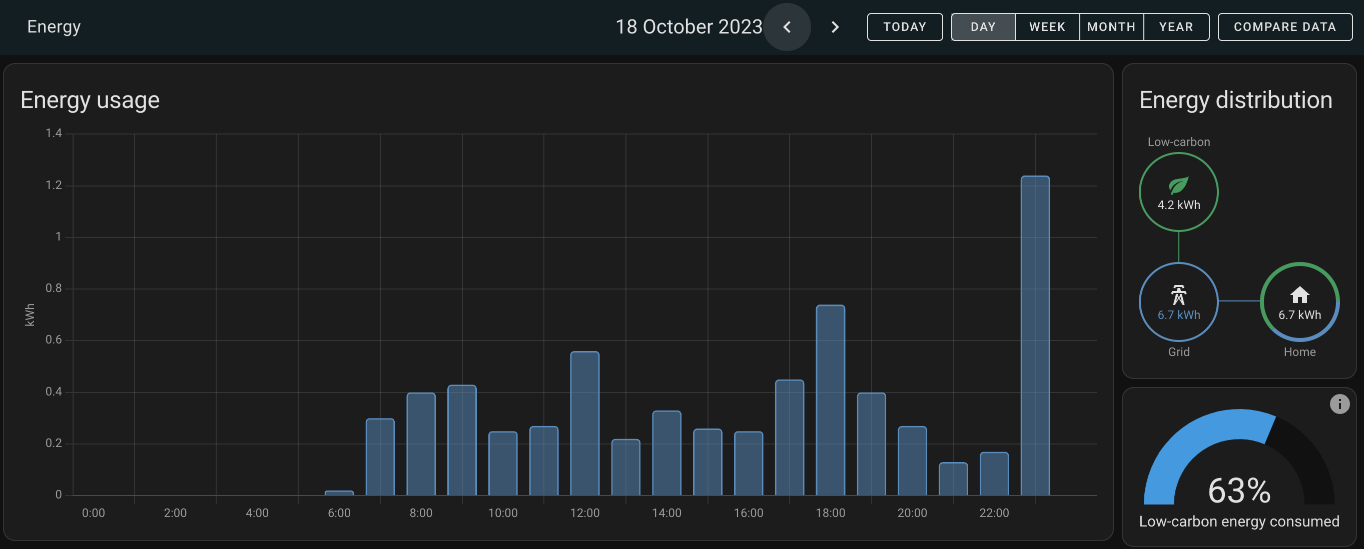
Once you’ve setup your device, we’ll want to create a sensor that converts the current usage which is measured in kiloWatts (kW) to a daily total which is measured in kiloWatt hours (kWh).
We’re going to use Home Assistant’s helpers to create two sensors to achieve this. Navigate to Settings -> Devices & Services -> Helpers and click + Create Helper.
Sensor #1 (Cumulative usage) – Select Integration – Riemann sum integral as the type of helper and then give it the following settings:
- Name: Cumulative electricity consumption (grid)
- Input Sensor: Current Grid Consumption (the ESPHome sensor you just created)
- Integration method: Left Riemann sum
- Metric prefix: None (default value)
- Time unit: hours (default value)
Sensor #2 (Today’s cumulative usage) – Create another helper with the type Utility Meter and give it the following settings:
- Name: Today’s electricity consumption (grid)
- Input Sensor: Cumulative electricity consumption (grid)
- Meter reset cycle: Daily
- Meter reset offset: 0 (default value)
- Supported tariffs: blank (default value)
- Net consumption: off (default value)
- Delta values: off (default value)
- Periodically resetting: on (default value)
Now you should be able to add the entity to your dashboard in Home Assistant 🎉
Adding the sensor to the Energy dashboard in Home Assistant
Navigate to Settings -> Dashboards -> Energy (don’t click open).
Under Grid consumption, click Add consumption and select Today’s Total Grid Consumption (the sensor that you have just created).
If you’re tracking your electricity cost in Home Assistant, you can set this before clicking Save.
*The product links in this post may contain affiliate links. I donate 20% of these earnings to the Good Work Foundation to help innovate learning in South Africa’s rural communities.
Thanks for making it to the end of the post!


This does not work for IR pulses.
I have tried following this, but it fails to detect any pulses. I believe this is because the LDR has almost no sensitivity in the IR spectrum pretty much all power meters i know of use for their pulses. It was not clear from this post that your smart meter was using visible light pulses instead of IR.
Hey @laund sorry about that. You might want to look for an IR receiver instead of an LDR. Most electricity meters in Ireland have red LED’s which is why I used an LDR.